wedNESday #5 - It's alive!
Posted on Wed 01 February 2017 in nes
First of all, I must thanks Toshimitsu Kamei, without him this post wouln't be possible. Some time ago, he helped me up connecting the RasberryPI's GPIO along with W65C02S. It was fun, although I was kind of clumsy in this meantime, and them now I have to reattach everything. So, let's do it.
The Ingredients
- Raspberry PI's 2 or 3
- Breadboard
- W65C02S
- Wires
- GPIO Expansion Board
You must use a Raspberry PI's 2 or above, due to the number of available GPIO ports. Using the GPIO Expansion Board is optional but highly recommended. The types of wiring that you might use depends if you be using or not the GPIO Expansion Board.
Wiring Up
Not really a big deal, however, you need to be carefull and patient. Raspberry PI's GPIO is not so fault tolerant as the Arduino is, any wrong connection on the ground or VCC and you might kill it. About the W65C02S, I'm not so sure, didn't burn any so far.
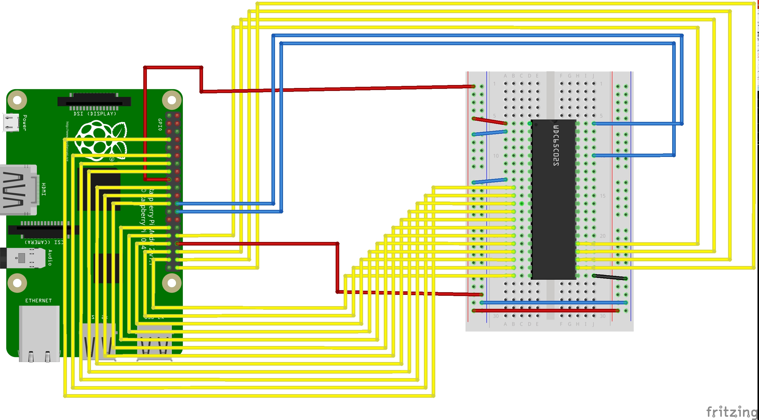
GPIO's connections
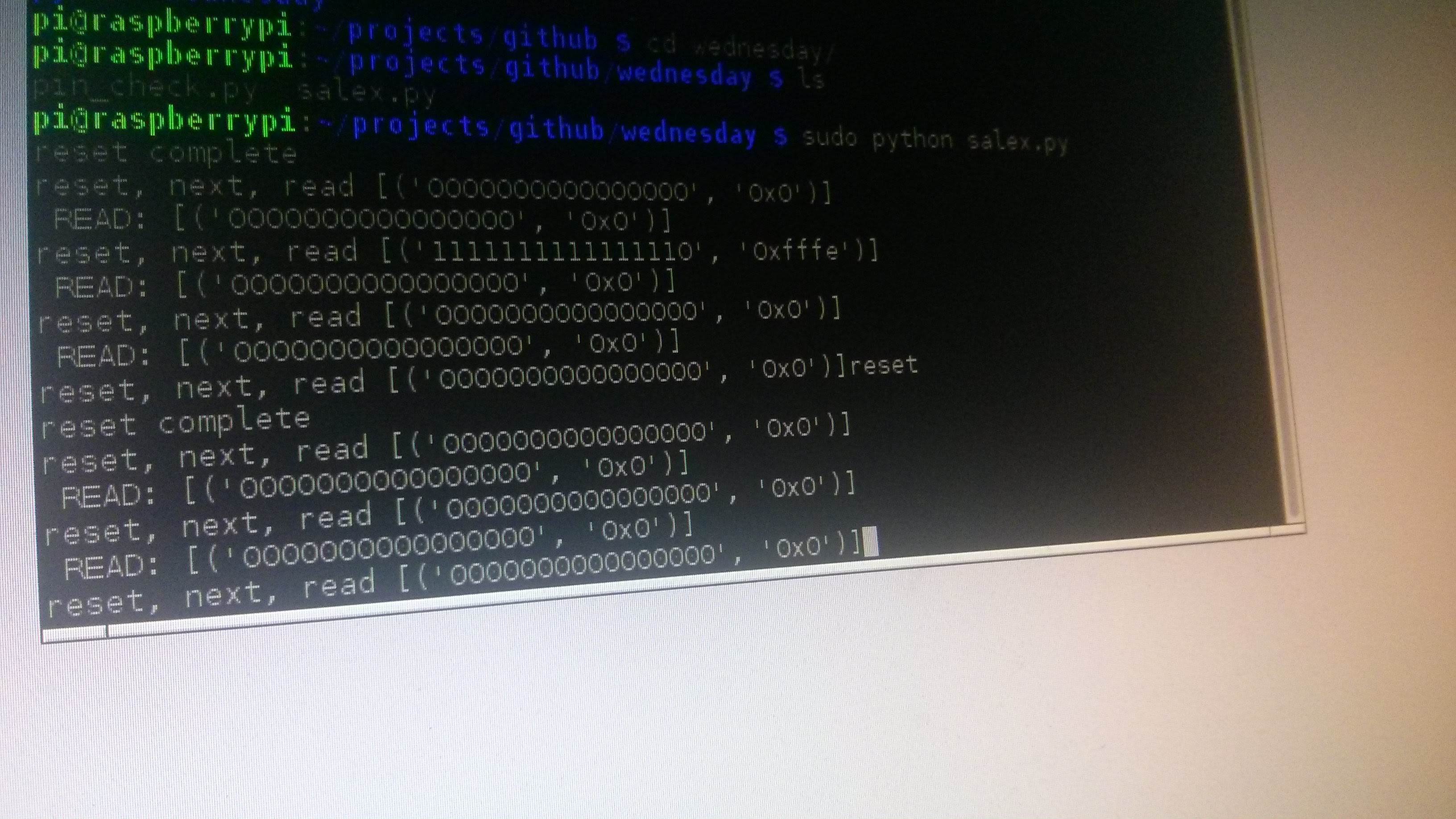
Hello World
Now that we got all connected, let's say hello. The following "Hello World" will read the address bus after the reset. When started, 6502 must read content from address 0xfffa, although, anything from 0xfffa to 0xfffe would be nice.
GPIO.setmode(GPIO.BCM)


ADDRESS_PINS = [
    4, 17, 27, 22, 10, 9, 11, 5, 6, 13, 19, 26, 21, 20, 16, 12
]

RESET_PIN = 8
CLOCK_PIN = 7


def terminate(signum, frame):
    GPIO.cleanup()
    sys.exit(0)

def setup():
    # Address pins
    for pin in ADDRESS_PINS:
        GPIO.setup(pin, GPIO.IN, pull_up_down = GPIO.PUD_DOWN)

    # Reset pin
    GPIO.setup(RESET_PIN, GPIO.OUT)

    # Clock PIN (PHI2)
    GPIO.setup(CLOCK_PIN, GPIO.OUT)

    # SIGINT
    signal.signal(signal.SIGINT, terminate)


def reset():
    GPIO.output(RESET_PIN, GPIO.HIGH)
    time.sleep(0.1)
    GPIO.output(RESET_PIN, GPIO.LOW)
    time.sleep(0.1)
    GPIO.output(RESET_PIN, GPIO.HIGH)
    print("reset complete")

def send_clock():
    time.sleep(0.1)
    GPIO.output(CLOCK_PIN, GPIO.LOW)
    time.sleep(0.1)
    GPIO.output(CLOCK_PIN, GPIO.HIGH)

def read_address():
    pin_state = ""
    for pin in reversed(ADDRESS_PINS):
        pin_state += str(GPIO.input(pin))

    hex_address = hex(int(pin_state, 2))
    return pin_state, hex_address

def read_address2():
    pins = [int(GPIO.input(pin) for pin in ADDRESS_PINS)]

    state = sum([int(cc) * (2 ** i) for i, cc in enumerate(reversed(pins))])
    return state, hex(state)

def main_loop():
    while True:
        address = read_address()

        input = None
        input = raw_input('("reset", (n)ext, "(r)ead"  [{}]> '.format(address))

        if input == "reset":
            reset()
        elif input == "r":
            print("READ!: [{}]".format(read_address()))

        else:
            print("READ!: [{}]".format(read_address()))
            send_clock()


if __name__ == "__main__":
    setup()
    reset()
    try:
        main_loop()
    except:
        terminate()
Not much to watch right now. You only be able to reset and check that it is reading the expected address. So far, we just acomplished a overside blinking led demo.
Upcomming Improvements
- The reset routine is not consistent. Sometime it jumps to 0xfff[a-e], sometime it doesn't.
- If you took a closer look on the wiring, you will notice that not all PINs were connected. I know, we are just connecting the address bus. We did not connected the data bus due the lack of available ports. That's why we can only hear from the address bus so far.
- We need to use some IO expander for sending data to address bus and data bus, that way will be using less ports on the Raspberry PI.